On a Pylontech installation, half of the "mysterious" faults at commissioning come neither from the batteries nor from the inverter, but from a single RJ45 cable plugged into the wrong port, or the wrong cable plugged into the right port. The inverter shows "battery not detected", the second battery never appears, the SOC stays frozen. This guide explains what each communication port of a Pylontech US2000, US3000C or US5000 does, the difference between a battery-to-battery and a battery-to-inverter cable, and the connection order that works.
There are two different cables, and they are not interchangeable. The battery-to-battery cable runs from LINK PORT 1 of one battery to LINK PORT 0 of the next (1 → 0, then 1 → 0, and so on). The battery-to-inverter cable leaves the CAN port (or RS485, depending on the inverter) of the master battery, and only that one. The CONSOLE port is used for neither.
Pylontech communication ports, one by one
On the front of a Pylontech US-series battery, next to the power terminals and the switch, there is a row of sockets that all look alike. They do completely different jobs:
| Port | Role | Cable to use |
|---|---|---|
| CAN | Talks to the inverter (CAN protocol), the most common on recent hybrid inverters | Battery-to-inverter, on the master battery only |
| RS485 | Talks to the inverter (RS485 protocol) for inverters that use it instead of CAN | Battery-to-inverter, on the master battery only |
| LINK PORT 0 | Input of the internal bus between batteries | Battery-to-battery, coming from LINK PORT 1 of the previous battery |
| LINK PORT 1 | Output of the internal bus to the next battery | Battery-to-battery, going to LINK PORT 0 of the next battery |
| CONSOLE | Service port (diagnostics, technician updates, monitoring devices) | Neither: console cable or dedicated device |
The exact order and labels vary slightly between models and generations, and some models have DIP switches that are set according to the configuration. Always trust the labels printed on your battery and its manual.
Master battery and slave batteries
In a bank of several Pylontech modules, only one battery talks to the inverter: the master battery. Through the internal LINK bus, it collects data from all the others (voltage, current, temperature, state of charge, alarms), then sends the inverter an overall picture of the bank: how much it can charge, how much it can discharge, what the average state of charge is.
The other batteries are slaves. They must never be connected directly to the inverter. If an inverter cable is plugged into a slave, the inverter receives partial data or nothing at all, and often goes into a communication fault.
The master is the battery at the head of the LINK chain: its LINK PORT 0 stays free, its LINK PORT 1 goes to the first slave. Follow the start-up procedure in your model's manual exactly during first commissioning.
The battery-to-battery cable (LINK)
This RJ45 cable carries the internal bus between modules. It always goes in the same direction:
- LINK PORT 1 of the master battery → LINK PORT 0 of slave no. 1;
- LINK PORT 1 of slave no. 1 → LINK PORT 0 of slave no. 2;
- and so on to the last battery, whose LINK PORT 1 stays free.
The most common mistake is plugging LINK 0 into LINK 0, or starting from the master's LINK PORT 0. Result: the second battery does not appear in the inverter, or the bank shows half its capacity.
The short cable supplied with the batteries is designed for stacked modules. As soon as batteries sit side by side or in two racks, you need a longer cable: our 3 m battery-to-battery RJ45 cable is made for that.
The battery-to-inverter cable (CAN or RS485)
This cable connects the CAN (or RS485) port of the master battery to the "BMS" or "Battery" port of the inverter. It lets the inverter control charging according to what the battery requests, instead of just measuring a voltage.
Why a special cable and not an ordinary network cable? Because the two ends do not necessarily use the same pins. On the Pylontech side, the CAN and RS485 signals are on specific pins of the RJ45 socket; on the inverter side, each manufacturer has chosen its own pinout. A straight network cable connects pin 1 to pin 1, pin 2 to pin 2… which matches some inverters and not others at all.
- Many hybrid inverters that support the Pylontech protocol (Goodwe, SMA, Huawei and others, depending on the model) accept the standard pinout of a Pylontech battery-to-inverter cable.
- Some inverters require their own cable. Victron, for example, uses a specific "VE.Can to CAN-bus BMS type B" cable for Pylontech batteries.
- On the inverter, you also need to select the right battery protocol (often "Pylontech" or "PYLON") in the settings.
For a Pylontech link to a compatible inverter, our 3 m battery-to-inverter RJ45 cable is wired for this purpose. If in doubt about your inverter, send us its exact model before ordering.
Never plug a battery-to-inverter cable between two batteries, or a LINK cable into the inverter. The two cables look alike, but their internal wiring is different. Label them during installation: it is the best way to avoid a mistake during later maintenance.
Complete wiring example: 3 Pylontech batteries
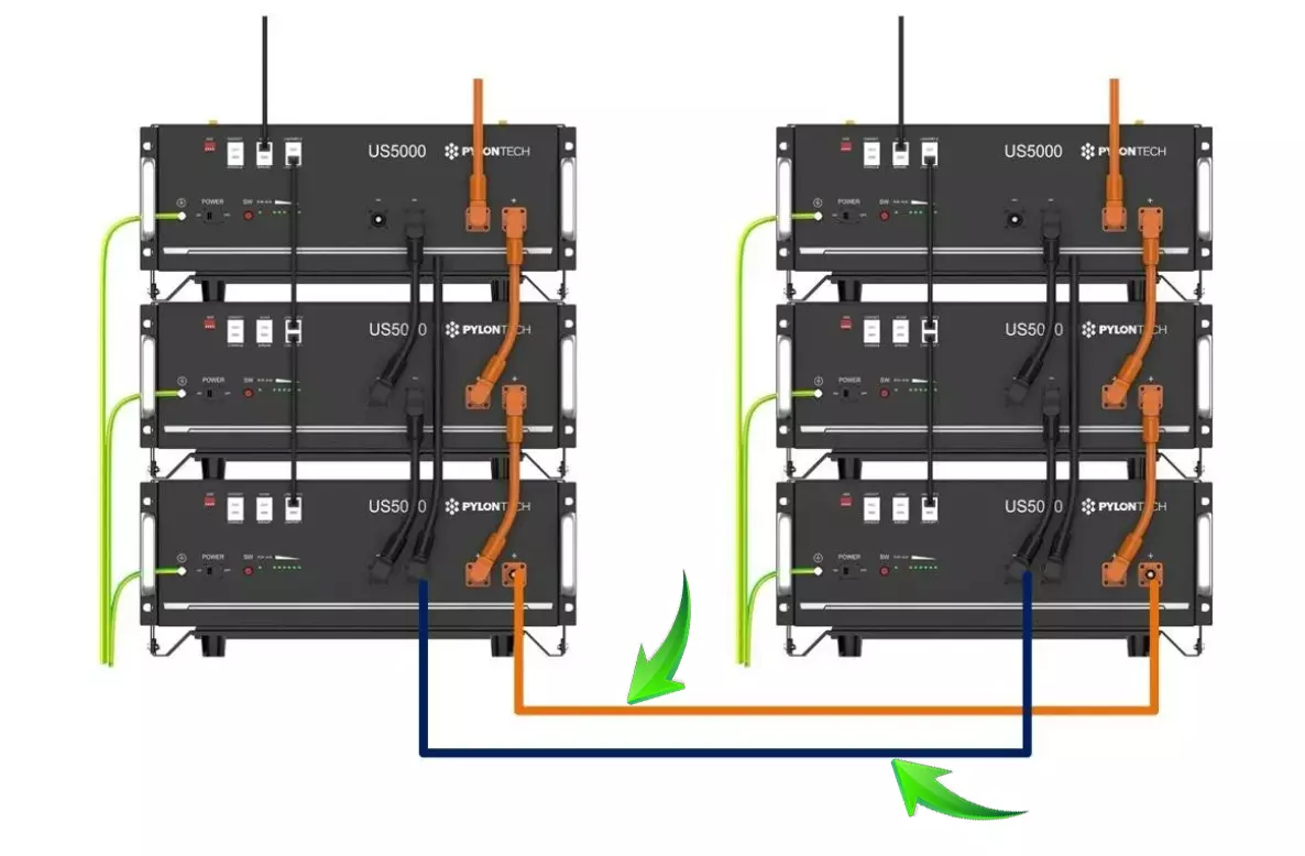
- Power: parallel cables between the batteries (positive to positive, negative to negative), ideally with the inverter positive on the first battery and the negative on the last. See our 48 cm parallel cables for stacked modules, or 1 m and 2 m for spaced modules.
- Internal bus: master LINK 1 → slave 1 LINK 0; slave 1 LINK 1 → slave 2 LINK 0.
- Inverter: master CAN (or RS485) → inverter BMS port.
- Free ports: master LINK 0, last slave LINK 1, slaves' CAN/RS485. Keep dust out with silicone RJ45 port covers.
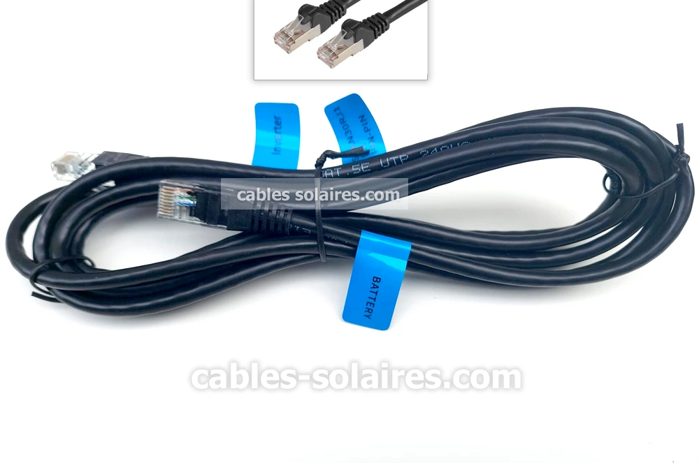
Both Pylontech RJ45 cables, 3 metres long
A battery-to-battery cable for the LINK bus, a battery-to-inverter cable for the CAN/RS485 link. Long enough for two racks or batteries side by side.
Symptoms of wrong wiring and how to fix them
| Symptom | Likely cause | What to check |
|---|---|---|
| Inverter shows "battery not detected" or "BMS communication error" | Inverter cable in the wrong port, wrong pinout, or wrong protocol setting | Cable on the CAN/RS485 port of the master, cable suited to the inverter, "Pylontech" protocol selected |
| Only some of the batteries appear (capacity too low) | LINK chain broken or reversed | LINK 1 → LINK 0 order along the whole chain, cables fully clicked in |
| Alarm on one slave battery only | Problem specific to that module (temperature, cell, power connection) | That module's power terminals, parallel cables, temperature |
| Intermittent communication | RJ45 plug not fully latched, crushed cable, or cable pulled tight against an edge | Replace with a new cable of the right length |
And the CONSOLE port, what is it for?
The CONSOLE port is a service port. It gives access to the detail of each battery: every cell voltage, temperatures, cycle count, state of health (SOH), alarm history. Technicians use it for diagnostics and updates. It does not replace the inverter cable and has nothing to do with the LINK bus.
It is also where a monitoring device such as the Pylon-Monitor (or its screenless version, the Pylon-Monitor Lite) plugs in, to see the state of every module and every cell from a phone, without touching the inverter wiring.
Frequently asked questions
Can I use an ordinary Ethernet cable between two Pylontech batteries?
Between batteries, on the LINK bus, a good-quality straight RJ45 cable usually works, but a cable that is too thin, poorly crimped or too long can cause communication drops. For the inverter, however, an ordinary Ethernet cable often does not work: the inverter-side pinout differs between brands.
Which inverter port should I use?
The port marked "BMS", "Battery" or "CAN" depending on the brand. The inverter manual tells you which port receives battery communication and which protocol to select.
Do I need an inverter cable on every battery?
No, never. Only the master battery is connected to the inverter. The others communicate with the master over the LINK bus.
CAN or RS485, which one should I choose?
Whichever your inverter uses. Most recent hybrid inverters communicate over CAN; some use RS485. Only plug in one of the two.
Do your RJ45 cables work with BYD or Goodwe Lynx?
No. Our RJ45 cables are designed for Pylontech US2000, US3000 and US5000 batteries. Other brands use their own communication wiring.